29+ deployment diagram components
Deployment diagrams are one of the two kinds of. To construct Component Diagram and Deployment Diagram to depict the structural view of the E-library Management.
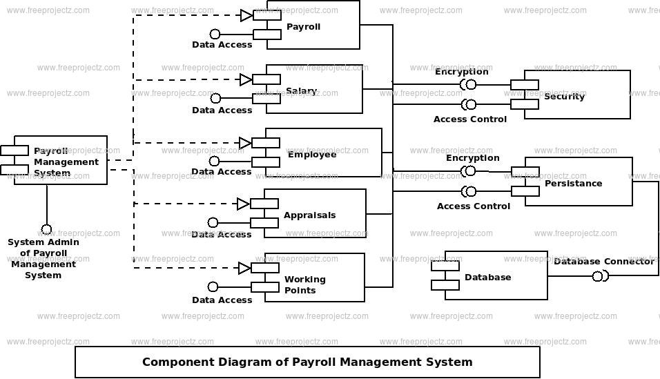
Deployment Diagram For Payroll Management System 31 Pages Summary 2 1mb Updated 2021 Alaia Books Chapter
The physical hardware is made up of nodes.
. Start the EdrawMax program. A component diagram defines the composition of components and artifacts. These diagrams are used to describe the physical components hardware their distribution and association.
A deployment diagram shows components and artifacts in relation to where they are used in the deployed system. Up to 24 cash back Pre-drawn UML deployment diagram symbols represent package object node component node instance component instance interface and. Deployment diagrams commonly contain Nodes and Dependency association relationships.
A Deployment diagram can be used to. View 29-Deployment Diagrams-29-Apr-2021Material_I_29-Apr-2021_deployment_diagrampdf from ITE 1007 at Vellore Institute of Technology. Deployment diagrams are mainly used by system engineers.
Graphically a deployment diagram is a collection of vertices and arcs. Component Diagram An example 9. A deployment diagram refers to a type of chart in the Unified Modeling Language that shows the relationship between nodes and artifacts.
A UML deployment diagram depicts a static view of the run-time configuration of hardware nodes and the software components that run on those nodes. It is primarily used by software engineers and. Show the structure of the run-time system.
INTRODUCTION UML component diagrams describe software components and their dependencies to each others A component is an autonomous unit within a system. Property was also extended in UML 20 with the capability. Capture the hardware that is going to be used to implement the system and links between different.
Deployment Diagram Describes the physical resources of the system hardware. Up to 24 cash back Here are the steps for the creation of deployment diagrams in the premium drawing software EdrawMax. Instance specification was extended in UML 20 to allow instance of a node to be deployment target in a deployment relationship.
This deployment diagram shows the relationships among software and hardware components involved in real estate transactions. Saquib Sheikh Roll No. A deployment diagram is a diagram that shows the configuration of run time processing nodes and the components that live on them.
Software runs on nodes Nodes can be PC.
2
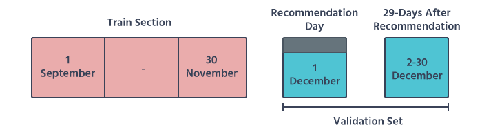
Building A Validation Framework For Recommender Systems A Quest By Dimitris Apostolopoulos Moosend Engineering Data Science Medium

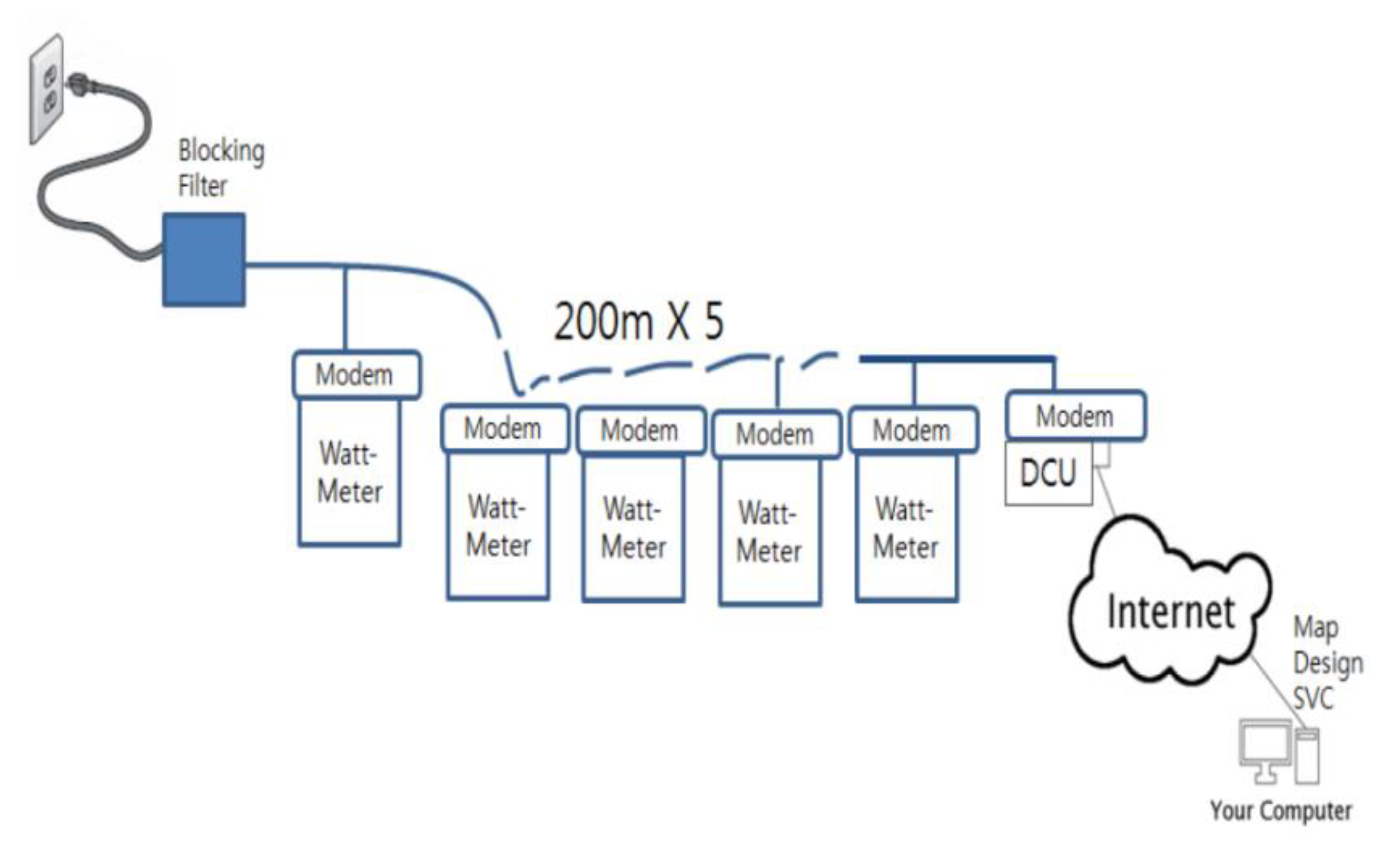
Alhena Technologies Intelligent Iot
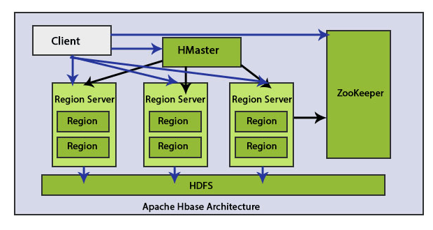
Hbase Architecture A Quick Glance Of Hbase Architecture
2
Sustainability Free Full Text Decrepit Building Monitoring Solution For Zero Energy Building Management Using Plc And Android Application Html
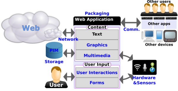
Standards For Web Applications On Mobile Current State And Roadmap

Learn Component Diagram For Food Ordering System Updated 2021 Elise Reviews And Ratings

Mosmb Smb With Mojo Mosmb Twitter
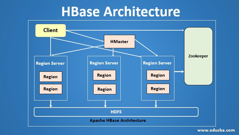
Hbase Architecture A Quick Glance Of Hbase Architecture
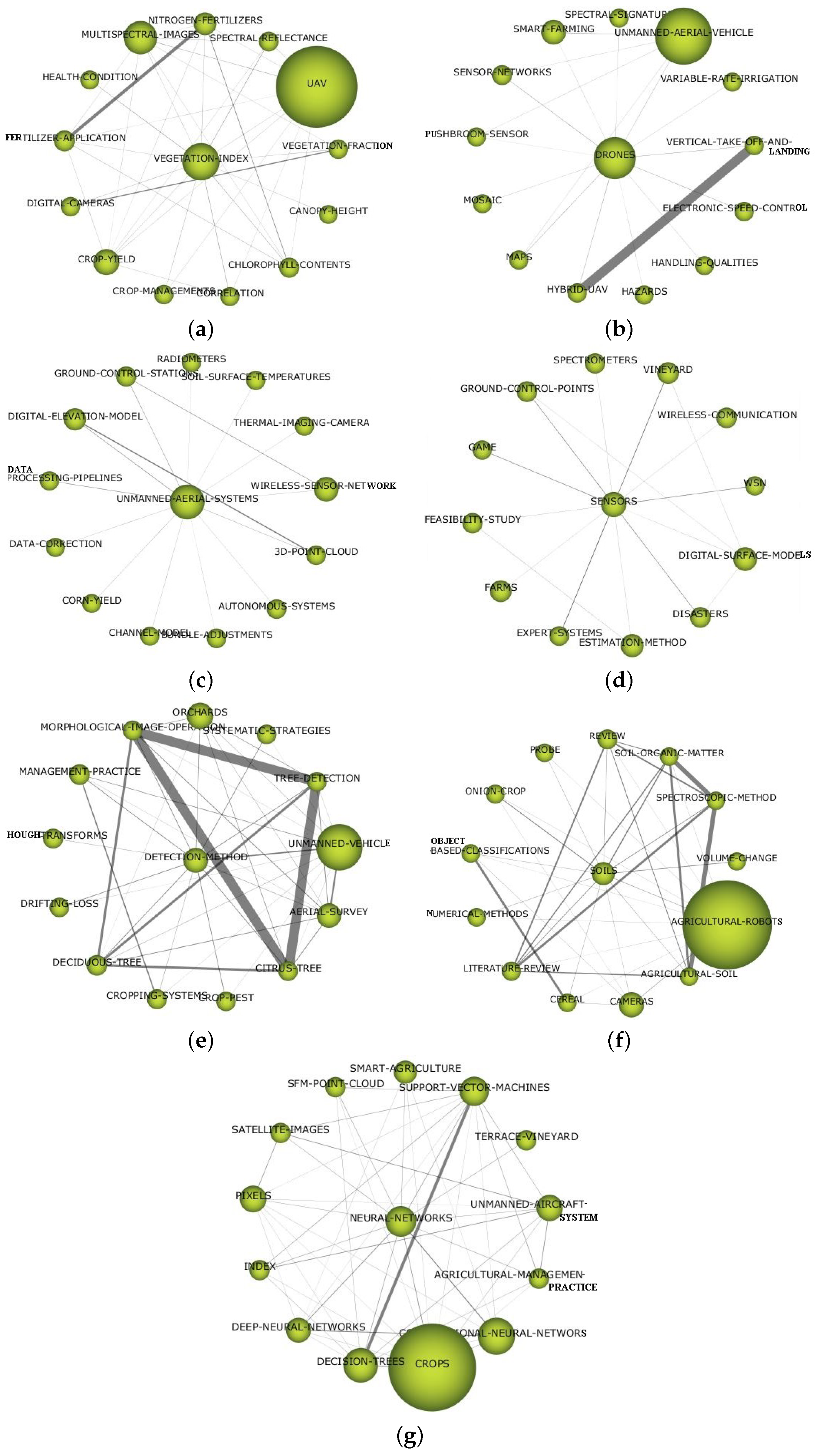
Remote Sensing Free Full Text A Bibliometric Review Of The Use Of Unmanned Aerial Vehicles In Precision Agriculture And Precision Viticulture For Sensing Applications Html
2
2015 Thai Military And Asian Region Page 8
2
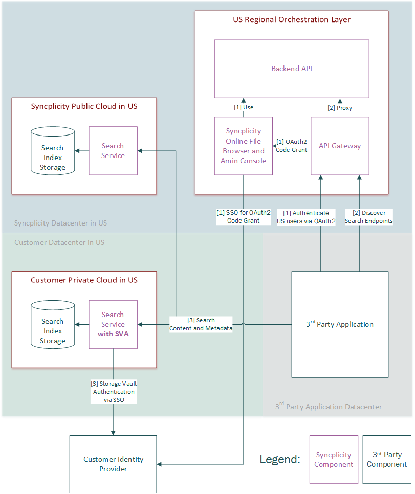
Syncplicity Api Portal
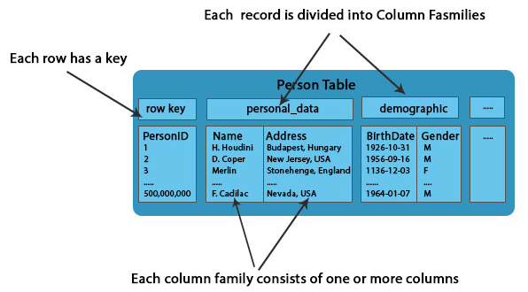
Hbase Architecture A Quick Glance Of Hbase Architecture

Deployment Diagram For Payroll Management System 31 Pages Summary 2 1mb Updated 2021 Alaia Books Chapter